
Online Catalog
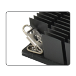
Accessory - QSZ clip
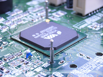
Heat Sinks are used to cool many devices (ASICS, FPGAs, CPUs, etc..). Each has a different mechanical and thermal requirement. To meet with these requirements, it is important to select an appropriate heat sink and attachment method.
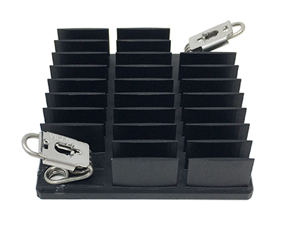
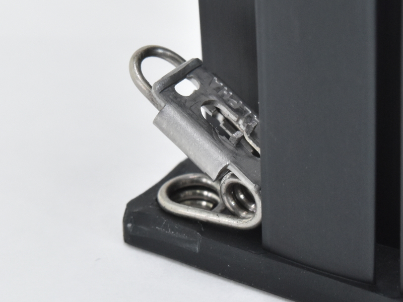
The QuickSet series was developed to meet these requirements. Heat Sinks are mounted directly to the PCB with anchor pins that take up a minimum of board real estate. Attachment forces and shock loads are transmitted to the PCB instead of the chip and solder balls. The torsion springs generate the appropriate attachment load and mounting pressure for the heat sink and thermal interface material.
Mounting pins only require 1.8mm[.071"] diameter holes in the PCB.
Heat sink comes pre-assembled with clip, ready for installation. Press and slide to install. Easy!
Attachment forces are transferred to the PCB instead of the device or solder balls.
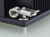
Heat sink location and orientation is precisely set by anchor pin.
Anchor pin locations can be changed without requiring a tooling/NRE fee.
By using different torsion springs and anchor pins, the appropriate attachment force can be generated.
Three torsion spring options are available. Individual torsion springs are NOT available as seperate part numbers.
| Model | Wire Diameter (mm) | Attachment force range per torsion spring (kgf) |
|
|---|---|---|---|
|
S001YZ4J | 0.8 | 1.0 ~ 1.3 |
| S001YZ4N | 0.9 | 1.4 ~ 1.9 | |
| S001YZ4M | 1.0 | 1.9 ~ 2.7 |
1st, Calculate X value (T) of graph, using the formula below the graph.
2nd, Y value (Force) can be found from the intersection of "X value (T)" and "Torsion spring performance
line".
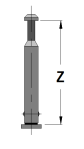
Anchor pins are captive and installed from the backside of the PCB. No solder is required.
| Model | Size Z (mm) |
Downloads | Availability / Price / Order | ||
|---|---|---|---|---|---|
| Data Sheet | Others | ||||
|
8 |
|
|
|
|
| 9 | |||||
| 10 | |||||
| 11 | |||||
| 12 | |||||
| 13 | |||||
| 14 | |||||
| 15 | |||||
| 16 | |||||
Removal procedure is the reverse of the installation procedure.
If a phase change material is used with the heat sink, unhook the hook plate from the anchor pin first. Warm the heatsink with a heat gun until the phase change temperature is reached. Gently remove the heat sink with a twisting motion. If the heat sink has to be re-installed, completely remove the phase change material from the heatsink and device before installing a fresh piece of phase change material.
Alpha can customize the QT series. Hole locations, overall height, etc.. can be changed without the need for a tooling/NRE fee. Please choose the heatsink and provide customization details to Alpha Sales.
© 2011 Alpha Novatech, Inc.