
Technical Information
Vapor Chamber Supplementary Information
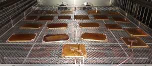
Our standard vapor chamber is structurally designed based on the assumption that the heat source is located at the center. For example, in the VC120, a sintered metal wick exists within an area of about 38 mm square at the center, and heat is assumed to spread from that point. However, in an actual use environment, the heat source is not necessarily located at the center. Even in such cases, vapor chambers tend to transfer heat over a wider area than copper plates. The video on the left compares the thermal diffusion between the vapor chamber and the copper plate at the same wattage, and a thermocouple placed inside the heater shows that the vapor chamber has a temperature 18.5°C lower than the copper plate.
This indicates that heat is not biased to one place and is spread efficiently.
Heat Source: 12x12mm 120W
Heat Sink(HS): ALPHA Custom LT130-40W
FAN: Oriental Motor MD1225-12DC
However, the thermal diffusion performance of a vapor chamber is not uniform under all conditions. Performance is highly dependent on the size and location of the heat source, as well as its positional relationship with the internal wick structure.
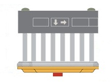
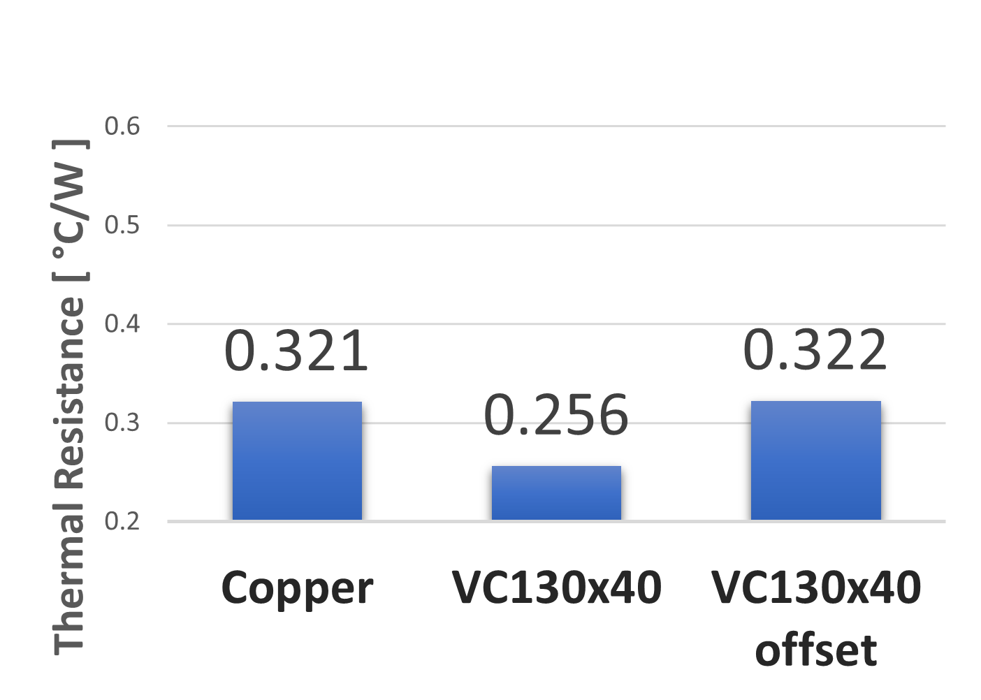
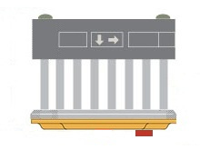
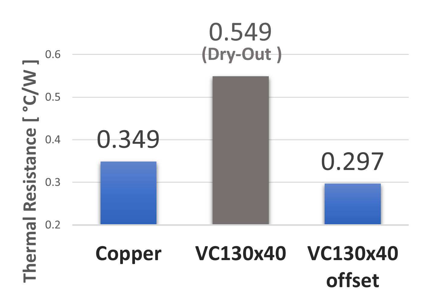
For example, the figure on the left compares performance based on different heat source positions for a 130 x 40 mm vapor chamber. In a vapor chamber designed with the assumption that the heat source is located at the center(VC130x40), dry-out occurs at a relatively low wattage if the heat source is placed at the edge.
In contrast, by optimizing the internal wick structure for edge-mounted heat sources(VC130x40 offset), performance is significantly improved under the same conditions.
Summary
- Compared to a copper plate, it spreads heat over a wider area and effectively suppresses the temperature rise at the heat source.
- Performance is highly sensitive to the location and size of the heat source. Optimization for actual operating conditions is essential.
In a sealed environment, liquid(water) heated at the evaporator section generally evaporates and moves as vapor, which then condenses into liquid at the condenser section. The condensed liquid is returned to the evaporator by capillary action, and this cycle naturally repeats itself. However, if the orientation (i.e., the direction of gravity) is opposite to the direction in which the liquid is returned by capillary force—such as when the vapor chamber is installed vertically as shown in the figure—there is concern that part of the liquid return may be hindered, potentially disrupting the heat transport cycle.
 horizontal placing
vertical placing
55
100
150
200
[ W ]
0.10
0.15
0.20
0.25
[ °C/W ]
horizontal placing
vertical placing
55
100
150
200
[ W ]
0.10
0.15
0.20
0.25
[ °C/W ]
The graph on the left shows the comparisons of thermal resistance of our heat sinks with fans and used vapor chambers in flat and vertical positions, respectively. As the graph on the left shows, there is little difference between the two in a particular wattage range. This result indicates that the thermal diffusion performance of our vapor chamber is effective under certain conditions.
Summary
- Regardless of the orientation of Alpha's vapor chamber, thermal diffusion is generally effective.
Dry-out is a phenomenon which occurs when excessive heat is generated by the heat source, and the circulation of cooling water by capillary action can't keep up. The working fluid completely evaporates in the evaporation section. If there is insufficient cooling water, dry-out occurs more easily, even at lower power levels. The graph on the left shows the relationship between supplied power and thermal resistance. Thermal resistance decreases (i.e., performance improves) as power increases. However, when the power level reaches approximately 400W, the graph reverses and indicates that thermal resistance increases due to dry-out.
Summary
- If heat dissipation is excessive, performance can be impacted due to dry-out.
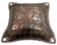
Our vapor chambers are designed for an operating temperature range of 10 to 90°C. However, based on our cycle test results, there's no significant change in functionality when testing up to 125°C. We have also confirmed that the thermal diffusion performance is maintained even after exposure to 170°C for 10 minutes. However, this test result is only an example and does not guarantee the thermal resistance performance of the product. However, when the temperature reached 180°C, the vapor chamber expanded as shown in the photo on the left. This occurs when the internal vapor pressure exceeds the structural limit of the support pillars. As a countermeasure, structural strength can be improved by increasing the diameter of the support pillars or the thickness of the plates. However, such modifications may affect other characteristics such as heat dissipation performance, so careful design consideration is required.
Summary
- Operating within the recommended temperature range is recommended.
- Exposure to excessive temperatures may cause the vapor chamber to expand.
We conduct cycle tests on our vapor chambers. It is made up of heating to 125°C and cooling to -40°C for 1000 cycles. Each cycle takes 35 minutes. The figure on the left shows the change in temperature over time.
The figure on the left shows the results of thermal resistance measurements after thermal cycling tests on our VC80 and a copper plate of the same size (80x80x3mm). This graph was made by measuring the workpiece multiple times every 250, 500, 750, and 1000 cycles, calculating the average value, and graphing the results.
A slight degradation in the performance of our vapor chamber was observed for some workpieces. This may be caused by repeated heating and cooling, which may have affected the flatness. However, the superiority of our product's performance compared to copper plate has been confirmed to be maintained.
Summary
- Repeated heating and cooling of the vapor chamber causes a slight deterioration in its performance.
- The performance advantage of our products over copper plates is maintained.
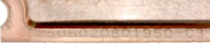
We perform helium leak tests (bombing method) and thermal tests on all manufactured workpieces. In addition, all products are given individual serial numbers, and water injection volume, measurement data, and test results are recorded and managed to ensure traceability.
Summary
- We ensure traceability in all of our products.
 Cross Section of Vapor Chamber
Contact surface dent:Max 0.5mm
Image
Cross Section of Vapor Chamber
Contact surface dent:Max 0.5mm
Image
Sintered parts are concentrated in the center of the vapor chamber. The flatness of this critical area in contact with the heat source is managed to within 0.05 mm. On the other hand, at the periphery, thermal distortion during bonding can cause indentations between the pillars. We allow concavities of 0.5 mm or less. In addition, spot welding may be temporarily performed for positioning during the assembly process, and weld marks resulting from such welding are also within the allowable range. However, if there is a concavity on the surface in contact with a heat source or heat sink that cannot be compensated for by the thermal interface, we treat the workpiece with such a protrusion as a defective product.
Summary
- Center part (25 mm square): Flatness within 0.05 mm.
- Surrounding area: The concavity is within 0.5 mm.
- Spot weld marks may remain on the product.
When assembling our vapor chambers to a heat sink, we use a thermal interface material between them and fasteners, or an adhesive with high thermal conductivity. We have conducted performance and reliability tests on our vapor chambers using SANYU REC's GRS-670, and have not observed any decline in performance under these conditions.
Summary
- Thermal interface material or thermally conductive epoxy is recommended for vapor chamber assembly.
 Lh
L
Wh
W
1.6
BOTTOM SURFACE CTR 25SQ
⌀C
⌀H
Lh
L
Wh
W
1.6
BOTTOM SURFACE CTR 25SQ
⌀C
⌀H
Customization of vapor chambers is based on the design of standard products. If the specifications are changed to the extent that the width or length differs, a prototype can be made within 2 weeks in a lot of 4 pieces at about $1000.00 per lot.
Summary
- For customization, please contact us.
© 2025 Alpha Novatech, Inc.