
Online Catalog
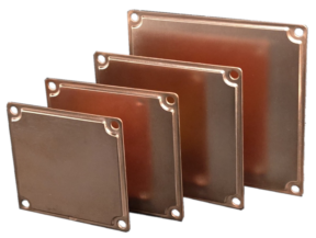
Vapor Chamber
- This series features high thermal conductivity vapor chambers.
- Vapor Chambers quickly spread high heat density over a wide area, enhancing cooling efficiency.
Comparison of Temperature Trends between the Vapor Chamber (VC120) and a Copper Plate.
Vapor Chamber
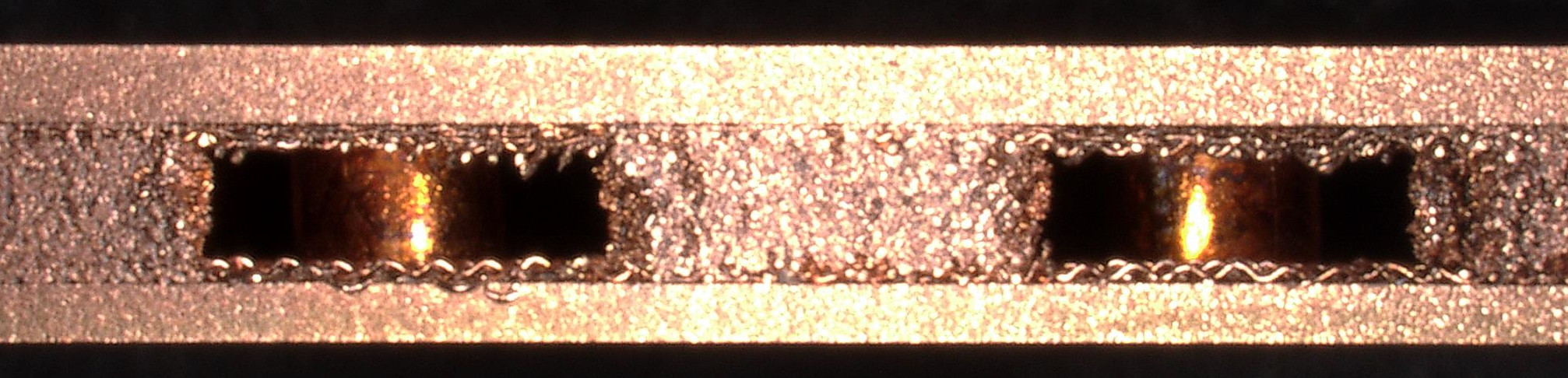
(Above picture shows Vapor Chamber cross section)
The inner wall of the thin copper container is bonded with a copper mesh, and a porous wick is placed at the heat source. The working fluid, pure water sealed under vacuum conditions, continuously evaporates and condenses, circulating through the wick by capillary action, efficiently dissipating heat.
The video on the left shows the temperature distribution when a 15x25mm heater is in contact with a product of 120mm square and 3mm thickness.
Compared to copper, the vapor chamber (VC120)
maintains a more uniform temperature over
a wider area, effectively suppressing
the temperature rise at
the heat source.
If the shape or size does not meet your requirements, please contact our sales department.
Supplement
- Working temperature range: 10 - 90°C.
| Model | Size W x L (mm) |
Corner R (mm) |
Hole Pitch X x Y (mm) |
Hole Dia ⌀H |
Weight (g) |
Download | Availability / Price / Order | ||
|---|---|---|---|---|---|---|---|---|---|
| Data sheet | Others | ||||||||
| - | 80 x 80 | 2.8 | 70 x 70 | 5.5 | 87.3 |
|
|
|
|
| - | 90 x 90 | 80 x 80 | 114.3 |
|
|||||
| - | 100 x 100 | 90 x 90 | 142.5 |
|
|||||
| - | 120 x 120 | 110 x 110 | 203.4 |
|
|||||
| - | 106 x 70 | 96 x 60 | 5.9 | 101.1 |
|
||||
| 60 x 60 | 10 | 49 x 49 | 2.8 | 49.1 |
|
||||
| 70 x 70 | 59 x 59 | 68.2 |
|
||||||
| 80 x 80 | 69 x 69 | 87.2 |
|
||||||
| 90 x 90 | 79 x 79 | 114.2 |
|
||||||
| 100 x 100 | 89 x 89 | 142.4 |
|
||||||
| 120 x 120 | 109 x 109 | 203.3 |
|
||||||
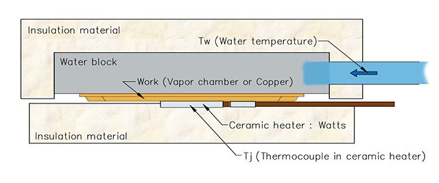
Measurement setup 1 (Bare die / Water cooling)
| Model | Power(W) | ||
|---|---|---|---|
| 100 | 200 | 400 | |
| VC80 | 0.094 | 0.088 | 0.08 |
| VC90 | 0.079 | 0.074 | 0.069 |
| VC100 | TBD | TBD | TBD |
| VC120 | 0.078 | 0.073 | 0.066 |
| VC106x70 | 0.091 | 0.086 | 0.077 |
| Without Vapor Chamber | 0.104 | 0.099 | 0.094 |
Heat source size : 15 x 25 (mm), Water flow rate 4.0 (L/min)
Measurement setup 2 (Bare die / Active fan)
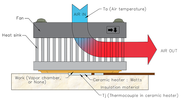
| Model (Combination) | Power(W) | |||
|---|---|---|---|---|
| Heatsink | Vapor Chamber | Fan | 55 | 100 |
| *1 FH10040A (Base 4mm thick, All Al) | VC90 | M92P | 0.404 | 0.384 |
| *2 FHC10040A (Al + Cu embedded) | - | 0.494 | 0.489 | |
| *3 FH10040A (All Al) | 0.610 | 0.609 | ||
*1 Custom FH10040A (Base thickness 4mm + VC 3mm = 7mm)
*2 Standard FHC10040A (Base thickness 7mm)
*3 Standard FH10040A (Base thickness 7mm)
| Model (Combination) | Thermal Resistance | |||
|---|---|---|---|---|
| Heatsink | Vapor Chamber | TIM | Power | (°C/W) |
| *1 LPD80-30B | VC60-H | TPCM5125 | 90 | 0.404 |
| VC70-H | 0.376 | |||
| VC80-H | 0.351 | |||
| *2 LPD80-30B | - | - | 0.599 | |
| *3 UB80-30B | VC60-H | TPCM5125 | 110 | 0.339 |
| VC70-H | 0.296 | |||
| VC80-H | 0.278 | |||
| *4 UB80-30B | - | - | 0.520 | |
Heat source size : 12 x 12 (mm)
Fan: AFB0812SH
*1 Custom LPD80-30B (Base thickness 2mm + VC 3mm = 5mm)
*2 Standard LPD80-30B (Base thickness 5mm)
*3 Custom UB80-30B (Base thickness 2mm + VC 3mm = 5mm)
*4 Standard UB80-30B (Base thickness 5mm)
| Model (Combination) | Thermal Interfaces | |||
|---|---|---|---|---|
| Heatsink | Vapor Chamber | TPCM5125 | *3 YG6260 | G751 |
| *1 FS12040W | VC60-H | 0.260 | ||
| VC80-H | 0.204 | |||
| VC90-H | 0.185 | |||
| VC100-H | 0.181 | 0.185 | 0.176 | |
| VC120-H | 0.173 | 0.166 | ||
| *2 FS12040W | - | 0.432 | ||
Heat source size : 12 x 12 (mm)
Power : 120 W
*1 Custom FS12040W (Base thickness 4mm + VC 3mm = 7mm)
*2 Standard FS12040W (Base thickness 7mm)
*3 Thermal Silicon Oil Compound
Contact | © 2025 Alpha Company Ltd.